
Commodore 64 Power Supply Pinout
Which contact on the C64's 7-pin DIN power socket carries +5V DC and which carries 9V AC, and how to test a supply before it reaches the machine.
August 24, 2026
The Commodore 64 is unusual among home computers of its generation: it needs two completely different kinds of power, and it takes both of them through a single 7-pin round DIN socket on the right-hand side of the case. Get one of those two wrong and the machine does not simply fail to start — it can be damaged beyond economical repair.
This page shows what sits on each contact, what the two rails are actually for, and how to check a supply before you plug it in.
Read this first. Contact positions are shown as you look into the socket on the computer, with the keyway at the top. Looking at the plug instead mirrors the picture left-to-right. If you are about to solder, confirm every rail with a multimeter on the actual hardware in front of you — not from a picture, this one included.
The power connector
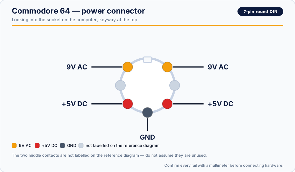
| Position | Rail |
|---|---|
| Upper left | 9V AC |
| Upper right | 9V AC |
| Middle left | not labelled on the reference diagram |
| Middle right | not labelled on the reference diagram |
| Lower left | +5V DC |
| Lower right | +5V DC |
| Bottom centre | GND |
Two things in that table surprise people.
The two 9V AC contacts are not duplicates. Alternating current has no fixed polarity, but it still needs two conductors — these are the two legs of the transformer's secondary winding. Both are labelled 9V AC because neither is "the positive one". You cannot leave one off and expect the machine to work.
The two +5V DC contacts are duplicates. A DIN contact of this size has a modest current rating, and the C64 pulls well over an amp on the 5V rail. Splitting that current across two contacts keeps each one inside its rating and cuts the voltage drop across the connector. The return path for both is the single GND contact at the bottom.
The two middle contacts are left unlabelled on the reference diagram. Treat them as unknown rather than as unused — measure them before you assume anything.
What each rail does
+5V DC — the dangerous one
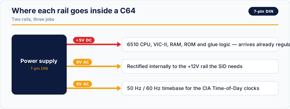
This is the rail that runs the digital side of the machine: the 6510 CPU, the VIC-II video chip, the RAM, the ROMs, the logic. It arrives from the power supply already regulated. There is no second regulator inside the C64 standing between the brick and the chips.
That single design decision is the reason the C64 has the reputation it has. In an original Commodore brick the 5V regulator sits potted in epoxy, cooked by its own heat for decades, and when it eventually fails it usually fails short — passing the unregulated input voltage straight through to the 5V rail. Ten or twelve volts arriving on a bus designed for five will take out RAM, the PLA, the SID and the CPU in the time it takes to notice the screen is wrong.
Anything you can do to catch that before it happens is worth doing. Measuring the rail is the cheapest insurance in retro computing.
9V AC — the one people forget
The 9V AC rail is left as alternating current on purpose, and the machine uses it for two separate jobs:
- It is rectified internally to make the +12V the SID sound chip and parts of the video circuitry need.
- Its 50 Hz or 60 Hz waveform drives the Time-of-Day clocks in the two CIA chips. The TOD counters literally count mains cycles.
The second point has a practical consequence: a machine running on a supply whose AC frequency does not match the region it was built for will keep bad time in software that uses the TOD clock. It is not a fault, it is arithmetic.
Original power supply specifications
The replacement supplies we build for the C64 target these figures:
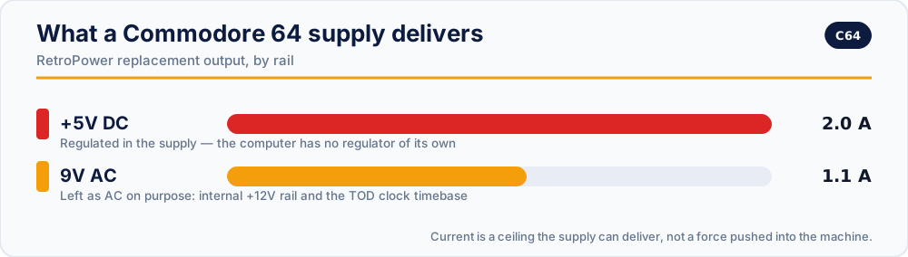
| Rail | Output | Notes |
|---|---|---|
| +5V DC | 2.0 A, stabilised, anti-ripple filtered | Regulated in the PSU, not in the computer |
| 9V AC | 1.1 A, transformer-generated | Feeds the internal +12V rail and the TOD clocks |
Both rails are fused, the DC side has over-voltage and over-current protection, and the two sides are fully isolated from each other.
Checking a supply before you trust it
Do this with the supply disconnected from the computer and plugged into mains, probing the plug itself.
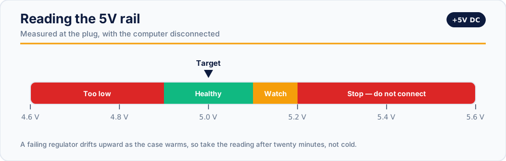
- Set the meter to DC volts. Measure between the lower-left contact and the bottom-centre GND contact. Expect a steady figure very close to 5.0 V.
- Repeat between the lower-right contact and GND. It should read the same.
- Switch the meter to AC volts. Measure between the two upper contacts — not between one of them and GND. Expect roughly 9 V AC.
- Watch the DC reading for a minute. A rail that drifts upward as the brick warms up is a rail that will keep drifting.
- Anything above about 5.2 V on the DC rail is a reason to stop. Do not connect it "just to test" — that test is what kills the machine.
Never judge a rail by wire colour. Replacement cables are made by many different people, and colour conventions are not one of them. The meter is the only thing that knows.
The Atari XL / XE trap
The Atari XL/XE uses the same 7-pin round DIN shell as the Commodore 64. The plugs mate perfectly, and nothing about the connector warns you.
What the Atari expects on those positions is +5V down the left column and ground down the right. A C64 supply puts 9V AC on the two upper contacts instead — applied to circuitry with no rectifier in front of it.
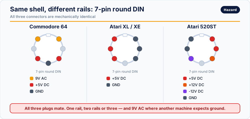
If a supply is not labelled for the machine in front of you, do not connect it.
Replacement supplies
If the measurements above did not go well, a modern regulated supply removes the failure mode entirely rather than postponing it:
- RetroPower PSU C64 — US plug · International plug
- RetroPower PSU C64 with OLED display — US plug · International plug
- C64 / C128 / FDD Ultimate — one supply for the whole family
Related reading
- Commodore 128 power connector pinout — same rails, different shell, and why that matters
- Retro power connectors: quick reference — every machine on one page
- Original vs modern power supply — what actually fails inside a vintage brick
Vintage power supplies carry mains voltage inside, and can hold dangerous charge after being unplugged. If you are not experienced with mains electricity, do not open one.