
Atari 520ST / 260ST Power Supply Pinout
The 520ST uses the same 7-pin round DIN as a Commodore 64 and an Atari XL/XE, and carries three rails where one of them carries one. Here is what sits on each contact.
August 15, 2026
There are three machines on this site whose power connector is a 7-pin round DIN, and they carry one, one and three rails respectively. The Atari 520ST is the three-rail one. The Commodore 64 and the Atari XL/XE are the others, and all three plugs mate perfectly with all three sockets.
Nothing mechanical prevents any of those six combinations. Only the label does.
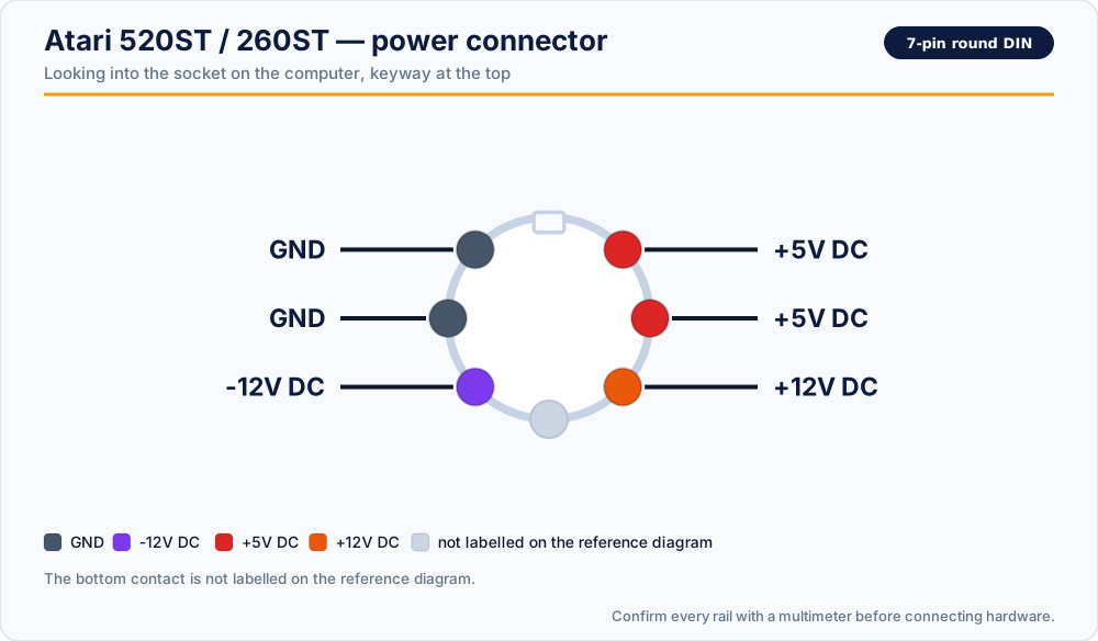
Read this first. Contact positions are shown as you look into the socket on the computer, with the keyway at the top. Looking at the plug instead mirrors the picture left-to-right. Confirm every rail with a multimeter before you solder anything.
The power connector
| Position | Rail |
|---|---|
| Upper left | GND |
| Middle left | GND |
| Lower left | -12V DC |
| Upper right | +5V DC |
| Middle right | +5V DC |
| Lower right | +12V DC |
| Bottom centre | not labelled on the reference diagram |
The layout is worth reading carefully, because it is almost — but not quite — symmetrical. The left column is two grounds and a negative rail; the right column is two +5V contacts and a +12V. The +5V rail is doubled across two contacts for the same reason it is tripled on an XL/XE: a DIN contact has a modest current rating, and splitting the load keeps each one inside it while cutting the voltage drop.
Both +5V contacts must be connected. A cable that wires only one will appear to work, run warm at the plug, and sag under load.
The three-machine trap
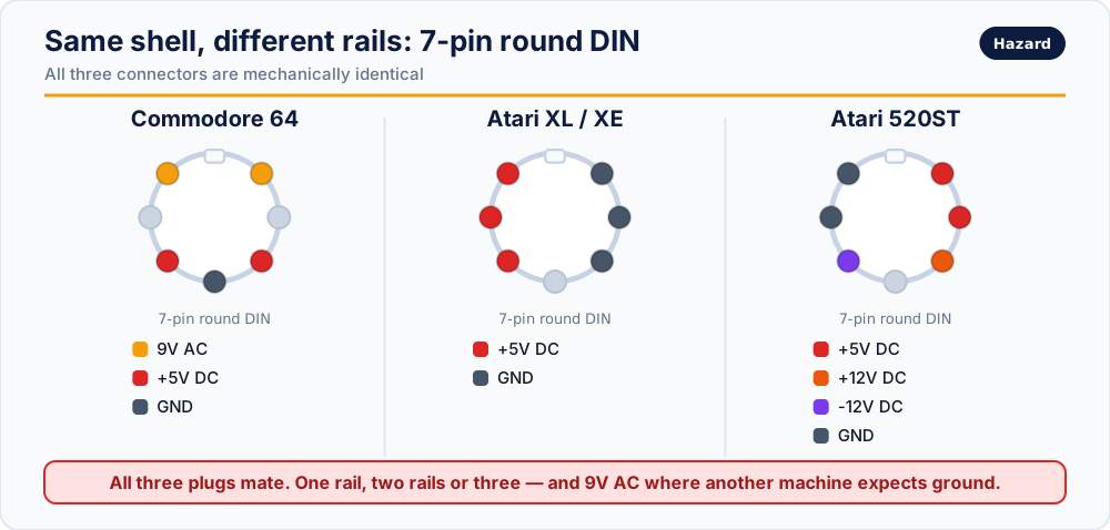
Read that diagram before building any cable. The same shell carries:
- Commodore 64 — +5V DC and 9V AC
- Atari XL / XE — +5V DC only
- Atari 520ST — +5V, +12V and −12V DC
Connecting a C64 supply to a 520ST applies 9V AC to contacts the ST expects to be ground and +5V. Connecting an XL/XE supply gives you 5V and nothing else, on a machine that needs three rails. Connecting a 520ST supply to an XL/XE puts +12V into a machine that has no 12V anywhere in it.
If a supply is not marked for the 520ST, do not connect it to one.
What each rail does
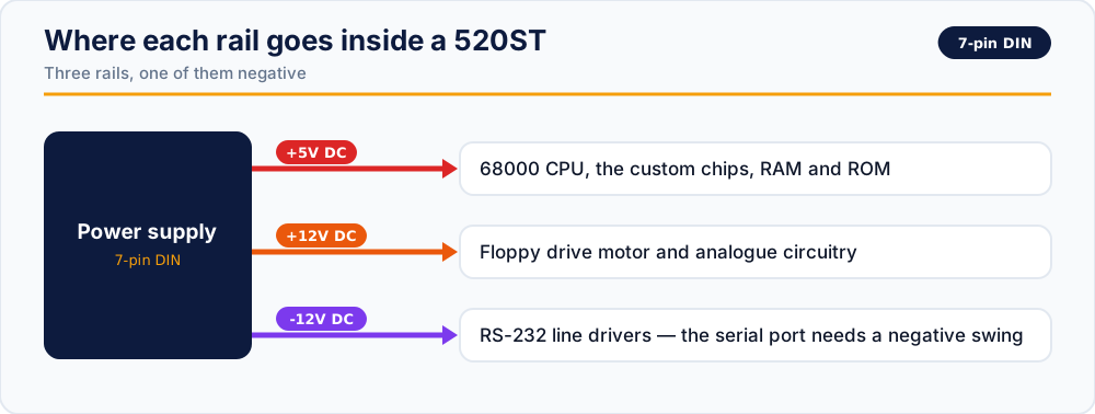
+5V DC
The 68000 and everything digital around it: the custom chips, RAM, ROM and glue logic. Nearly all of the current lives here.
+12V DC
The floppy drive motor and the analogue circuitry. As with every motor rail, the number that matters is the peak on spin-up rather than the average — a supply that measures correctly at idle can still dip enough at that moment to produce a read error.
-12V DC — small, and not optional
Half an amp at most, and it exists for the RS-232 line drivers. The serial standard requires the signal to swing both above and below ground, so a compliant port needs a negative supply to produce it.
The failure mode is the confusing one: a machine with a dead −12V rail boots, runs software perfectly, and fails only when something touches the serial port. That looks like a software problem, or a cable problem, or a peripheral problem. It is a power problem.
What our replacement delivers
| Rail | Output |
|---|---|
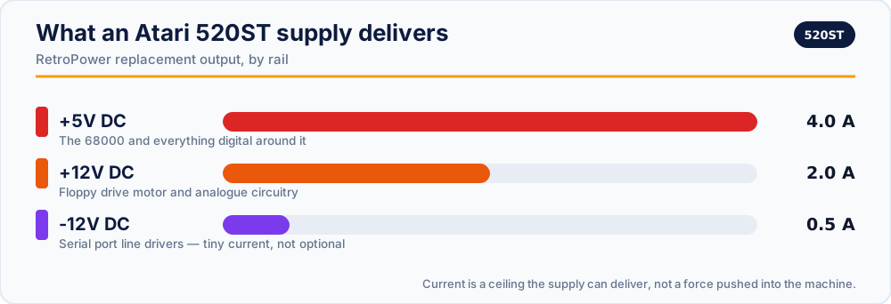
| +5V DC | 4.0 A, stabilised |
| +12V DC | 2.0 A, stabilised |
| -12V DC | 0.5 A, stabilised |
With over-voltage and over-current protection, fusing on both the AC and DC sides, and full isolation.
Checking a supply before you trust it
With the supply on mains and disconnected from the computer, probe the plug. All measurements are taken against either of the left-column ground contacts.
- Upper-right to GND: expect close to +5.0 V. Repeat for middle-right — both should read the same. A difference means a broken conductor in the cable.
- Lower-right to GND: expect close to +12.0 V.
- Lower-left to GND: expect close to −12.0 V. A positive reading here means either your leads are reversed or the supply is — and in the second case, do not connect it.
- Confirm there is no AC anywhere on the connector. If your meter reads volts on the AC range, you are holding a Commodore supply.
- Watch all three for a minute. Upward drift on the 5V rail as the case warms is a failing regulator.
Replacement supplies
- RetroPower PSU Atari 520ST/260ST — US plug · International plug
- RetroPower PSU Atari 520ST/260ST with OLED display — US plug · International plug
Related reading
- Atari XL / XE power supply pinout — the same shell, one rail
- Commodore 64 power supply pinout — the same shell again, with AC on it
- Retro power connectors: quick reference
Vintage power supplies carry mains voltage inside, and can hold dangerous charge after being unplugged. If you are not experienced with mains electricity, do not open one.