
Amiga CD32 Power Supply Pinout
What sits on each contact of the Amiga CD32's 4-pin round DIN power connector, why it needs only two rails where an A500 needs three, and how to test a supply before connecting it.
August 23, 2026
The CD32 is the odd Amiga. It shares a chipset generation with the A1200 but it is a console, and its power connector reflects that: a small 4-pin round DIN carrying two DC rails, where an Amiga 500 needs a 5-pin shell and three.
That makes it the simplest Amiga to power — and the one most often given the wrong supply, because a connector with fewer contacts looks like it must be less demanding.
Read this first. Contact positions are shown as you look into the socket on the console, with the keyway at the top. Looking at the plug instead mirrors the picture left-to-right. Confirm every rail with a multimeter before you solder anything.
The power connector
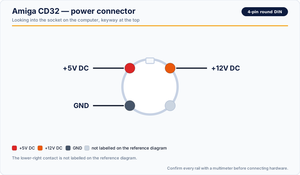
| Position | Rail |
|---|---|
| Upper left | +5V DC |
| Upper right | +12V DC |
| Lower left | GND |
| Lower right | not labelled on the reference diagram |
Three of the four contacts are accounted for. The fourth is left unlabelled on the reference diagram — measure it rather than assuming it is dead, and do not connect anything to it on a cable you are building.
What each rail does
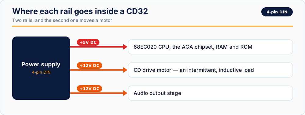
+5V DC — nearly all of the current
The 68EC020, the AGA chipset, Akiko, the RAM and the ROM all run from this rail. On a console with no expansion slots to speak of, this is where essentially the entire load sits.
+12V DC — the motor rail
Two jobs, and the first one is what makes this rail interesting: it turns the CD drive.
A disc motor is an intermittent, inductive load. It draws a spike when it spins up and again on every seek. A supply that measures perfectly at idle can still dip badly at exactly those moments, and on a CD32 the symptom is a read error or a lock-up during loading rather than a machine that refuses to start. If your CD32 boots fine and then fails part-way into a game, the 12V rail under load is the first place to look.
It also feeds the audio output stage.
What our replacement delivers
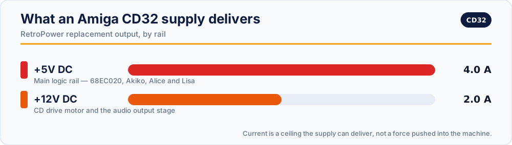
| Rail | Output |
|---|---|
| +5V DC | 4.0 A, stabilised |
| +12V DC | 2.0 A, stabilised |
With over-voltage and over-current protection, fusing on both the AC and DC sides, and full isolation between them.
Note the 12V figure. It is sized well above what the drive motor needs at rest, because the number that matters for a CD32 is not the average draw but the peak on spin-up.
Checking a supply before you trust it
With the supply on mains and disconnected from the console, probe the plug. Both measurements are taken against the lower-left GND contact.
- Upper-left to GND: expect close to +5.0 V.
- Upper-right to GND: expect close to +12.0 V.
- Check the unlabelled lower-right contact against GND as well, so you know what is on it.
- Watch both rails for a minute. Drift upward on the 5V rail as the case warms is a failing regulator.
- Above roughly 5.2 V on the 5V rail, stop.
A CD32 supply is not an A500 supply. The A500 shell is a 5-pin square DIN carrying +5V, +12V and −12V. The CD32 shell is a 4-pin round DIN carrying two rails. They do not mate, and that is the only thing preventing the mistake — so do not defeat it with an adapter.
Replacement supplies
- RetroPower PSU Amiga CD32 — US plug · International plug
- RetroPower PSU Amiga CD32 with OLED display — US plug · International plug
Related reading
- Amiga 500 power supply pinout — the three-rail sibling
- Retro power connectors: quick reference
- Which power supply do I need?
Vintage power supplies carry mains voltage inside, and can hold dangerous charge after being unplugged. If you are not experienced with mains electricity, do not open one.