
Amiga 500 Power Supply Pinout
What sits on each contact of the Amiga 500 square 5-pin DIN power connector, what the -12V rail is for, and what the original bricks delivered.
August 12, 2026
Where a Commodore 64 wants one DC rail and an AC rail, the Amiga 500 wants three DC rails at once — and one of them is negative. All four conductors plus a shield arrive through a single square 5-pin DIN connector, which means every contact on that connector matters and none of them are spare.
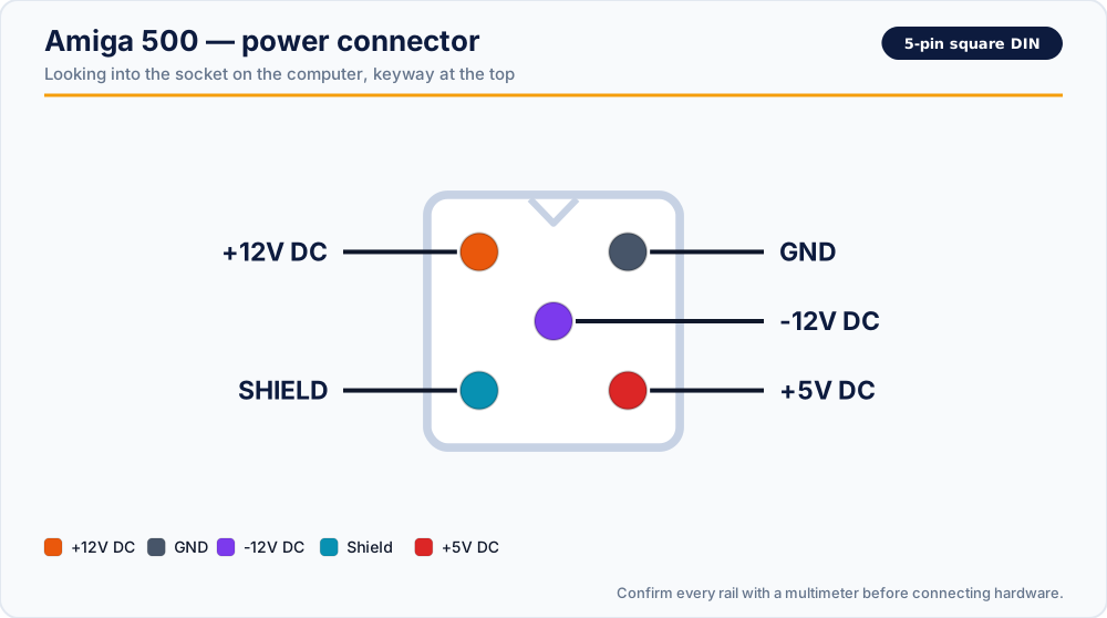
Read this first. Contact positions are shown as you look into the socket on the computer, with the keyway at the top. Looking at the plug instead mirrors the picture left-to-right. Confirm every rail with a multimeter before you solder anything — a supply that puts +12V where the machine expects -12V will do damage instantly.
The power connector
| Position | Rail |
|---|---|
| Upper left | +12V DC |
| Upper right | GND |
| Centre | -12V DC |
| Lower left | Shield |
| Lower right | +5V DC |
Every contact is accounted for on this one — there are no unlabelled positions to worry about.
Note that the shield is a contact in its own right, not a bonus. It terminates the cable screen, and leaving it floating on a replacement cable is a common cause of otherwise inexplicable video interference and serial port errors.
What each rail does
+5V DC — the workload
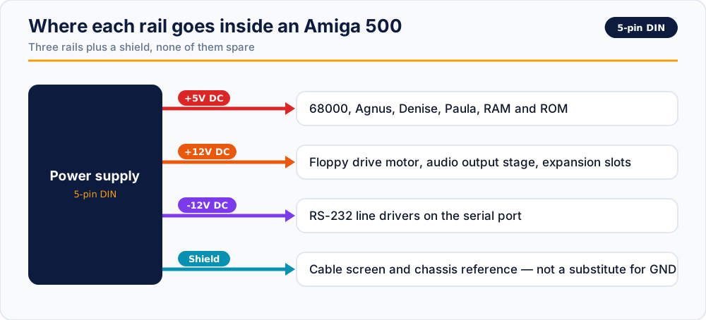
The main logic rail: the 68000, Agnus, Denise and Paula, the RAM, the ROM, and everything else digital. This is where nearly all the current goes, and it is the rail whose sag shows up first as random guru meditations under load.
+12V DC
Drives the floppy drive motor, the audio output stage, and parts of the video circuitry. It is also the rail present on the expansion connectors, so an accelerator or a hard drive controller may draw from it.
The floppy motor is the interesting load here: it is intermittent and inductive. A supply that measures perfectly at idle can still dip badly at the moment the drive spins up, and on an Amiga that dip is a read error rather than a crash.
-12V DC — the small rail with a specific job
Only a small current, and easy to dismiss — but the RS-232 line drivers on the serial port need a negative supply to produce a compliant signal swing. A machine with a dead -12V rail boots, runs games happily, and then fails only when something tries to use the serial port. That makes it one of the more confusing faults to chase.
Shield
Cable screen and chassis reference. Not a power rail, and not a substitute for GND.
What the original Commodore supplies delivered
Different Amiga models and PSU revisions shipped with different capabilities. If you are matching a replacement to a machine, this is the table that matters:
| PSU type | Part number | +5V | +12V | -12V | Combined |
|---|---|---|---|---|---|
| A500 Type 1 | 312503-02 | 2.5 A | 1.0 A | 0.1 A | 25.7 W |
| A500 Type 2 | 312503-03 | 4.5 A | 1.0 A | 0.1 A | 35.7 W |
| A600 / A1200 | 391029-02 | 3.0 A | 0.5 A | 0.1 A | 22.2 W |
| A600 / A1200 | 391029-03 | 3.0 A | 0.5 A | 0.1 A | 22.2 W |
Two observations worth drawing out. The early A500 brick delivers barely half the 5V current of the later one — an original Type 1 supply running a fully expanded A500 is working far harder than its designer intended. And the A600/A1200 supplies give up +12V capacity in exchange for a machine that needs less of it, which is why they struggle when asked to run an A500 with a second floppy drive.
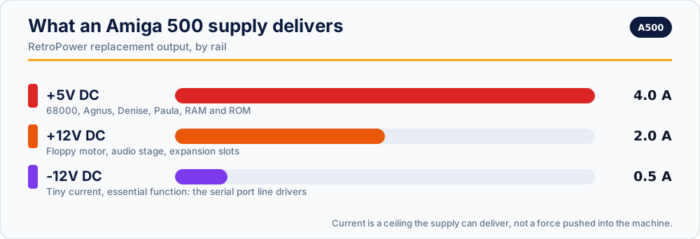
Our replacement supplies for the A500 target +5V/4.0A, +12V/2.0A and -12V/0.5A, with over-voltage and over-current protection, fusing on both AC and DC sides, and full isolation.
The Commodore 128 shares this shell
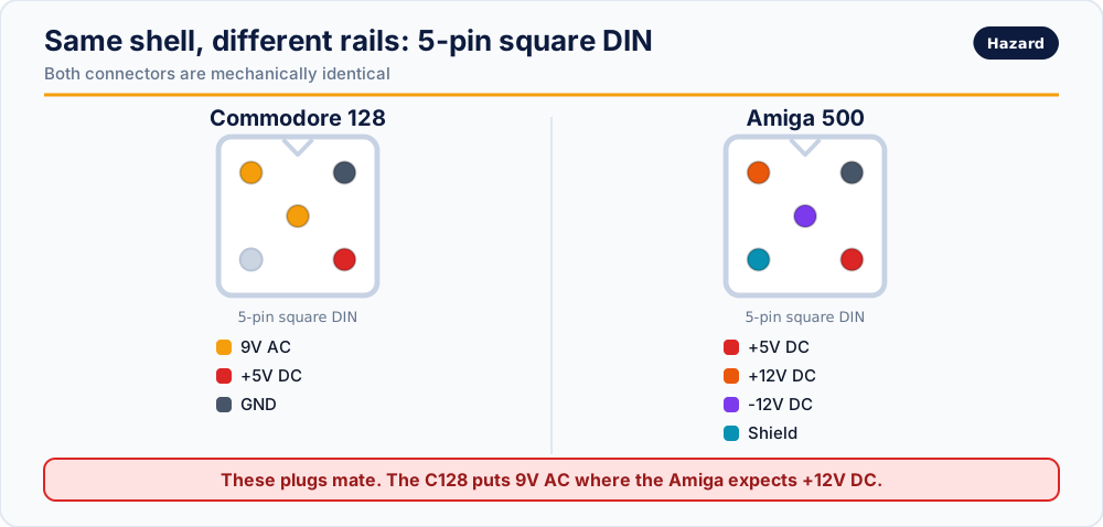
The 5-pin square DIN is not unique to the Amiga. A Commodore 128 supply uses the same shell and will mate with an Amiga 500 socket — while putting 9V AC where the machine expects +12V DC, and nothing at all where it expects -12V.
Checking a supply before you trust it
With the supply on mains and disconnected from the Amiga, probe the plug. All DC measurements are taken against the upper-right GND contact.
- Lower-right to GND: expect close to +5.0 V.
- Upper-left to GND: expect close to +12.0 V.
- Centre to GND: expect close to -12.0 V. If your meter shows a positive number here, the leads are reversed — or the supply is, and that is a supply you must not connect.
- Check the shield contact for continuity to the cable screen, and confirm it is not shorted to any rail.
- Watch all three rails for a minute. Drift upward on the 5V rail as the case warms is a failing regulator.
Cable colours are not a specification. Replacement leads are built by many different people to no shared convention, and a "standard" colour table found online may not describe the lead in your hand. Measure.
Replacement supplies
- RetroPower PSU Amiga 500 — US plug · International plug
- RetroPower PSU Amiga 500 with OLED display — US plug · International plug
- RetroPower PSU Amiga CD32 — US plug · International plug
Related reading
- Retro power connectors: quick reference — every machine on one page
- Volts, amps and 9V AC explained — how to read a PSU specification
- Original vs modern power supply
Vintage power supplies carry mains voltage inside, and can hold dangerous charge after being unplugged. If you are not experienced with mains electricity, do not open one.