
Commodore 64 and Amiga Connector Pinouts blog
A practical reference guide to common Commodore 64 and Amiga connector pinouts, including power, video, joystick, serial and other connectors.
July 30, 2026
Commodore 64 and Amiga Connector Pinouts
This page provides a quick reference to some of the most commonly used connectors found on the Commodore 64 and classic Commodore Amiga computers.
Warning: Always verify connector orientation and pin numbering before connecting any hardware. When working with power supplies, measure the actual voltages with a multimeter before connecting the PSU to the computer.
Commodore 64
The Commodore 64 uses several different connectors for power, video, joysticks, serial peripherals, the Datasette, the User Port and expansion cartridges.
Power Connector
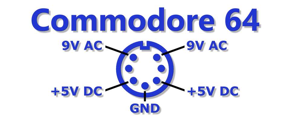
The Commodore 64 uses a dedicated power connector providing two voltage rails:
- +5V DC
- 9V AC
The 5V DC rail is particularly important because an incorrect or excessive voltage can damage components on the C64 motherboard.
Before connecting an original or replacement PSU, it is strongly recommended to measure the output voltages with a multimeter.

Important: Never rely solely on cable colours when identifying power connections. Always verify the actual voltage and polarity with a multimeter.
A/V Connector
The Commodore 64 uses an 8-pin DIN connector for audio and video output.
Depending on the cable and display device, the connector can provide:
- Composite video
- Luma
- Chroma
- Audio
- Ground
The exact signal configuration depends on the cable being used and the video input required by the display.
Joystick Ports
The Commodore 64 has two joystick ports using 9-pin connectors.
The ports support standard digital joysticks with:
- Up
- Down
- Left
- Right
- Fire button
Joystick Port 1
Joystick Port 1 is connected to CIA 1 Port B.
Joystick Port 2
Joystick Port 2 is connected to CIA 1 Port A.
The joystick interface can also be used for custom hardware projects and other digital I/O applications.
Serial Port
The C64 serial port is used to connect peripherals such as:
- Commodore 1541 disk drive
- Commodore 1571 disk drive
- Commodore 1581 disk drive
- Commodore printers
The serial interface uses Commodore's proprietary serial bus protocol.
Datasette Connector
The Datasette connector is used to connect Commodore cassette tape drives such as:
- Commodore 1530 Datasette
- Commodore 1531 Datasette
The connector carries the signals required for cassette data communication, motor control and power.
User Port
The Commodore 64 User Port provides direct access to I/O lines from CIA 2.

The User Port can be used for:
- Custom electronics
- Digital I/O
- Serial interfaces
- Modems
- Printers
- Hardware experiments
The User Port is particularly useful for retro-computing hardware projects because it provides direct access to the computer's I/O subsystem.
Expansion Port
The Commodore 64 expansion port allows external hardware to communicate directly with the computer.
Common uses include:
- Game cartridges
- Memory expansions
- Diagnostic cartridges
- Fast loaders
- Modern cartridge interfaces
The expansion port provides access to the system bus and is widely used by modern C64 hardware projects.
Amiga
Classic Commodore Amiga computers use several different connectors depending on the model.
This section focuses primarily on the external power supply connector commonly used by systems such as:
- Amiga 500
- Amiga 500+
- Amiga 600
- Amiga 1200
Amiga Power Supply Connector
The classic external Amiga power supply provides three main voltage rails:
- +5V
- +12V
- -12V
The commonly reported cable colours are:
| Cable Colour | Function |
|---|---|
| Black | GND / Ground |
| Brown | +12V |
| White | -12V |
| Red | +5V |
| Yellow | Shield |
Important: Cable colours may differ between power supplies and replacement cables. Always verify the actual voltage and polarity with a multimeter before connecting the PSU to your Amiga.
Original Amiga Power Supply Output
Different Amiga models and PSU revisions were supplied with different current capabilities.
| PSU Type | Part Number | +5V | +12V | -12V | Combined Power |
|---|---|---|---|---|---|
| A500 Type 1 | 312503-02 | 2.5A | 1.0A | 0.1A | 25.7W |
| A500 Type 2 | 312503-03 | 4.5A | 1.0A | 0.1A | 35.7W |
| A600 / A1200 | 391029-02 | 3.0A | 0.5A | 0.1A | 22.2W |
| A600 / A1200 | 391029-03 | 3.0A | 0.5A | 0.1A | 22.2W |
When replacing an original PSU, make sure the replacement provides:
- The correct voltage levels.
- Correct polarity.
- Sufficient current capacity.
- The correct connector and pinout.
- Proper grounding and shielding.
Safety
Vintage power supplies should be treated with caution.
Before connecting a PSU to a Commodore or Amiga computer:
- Inspect the PSU for visible damage.
- Check the power cable and connector.
- Verify the connector pinout.
- Measure all output voltages with a multimeter.
- Confirm the polarity of every voltage rail.
- Check for shorts between adjacent pins.
- Connect the PSU to the computer only after all measurements are correct.
When working with mains-powered power supplies, dangerous voltages may be present even after the PSU has been disconnected from mains power.
If you are not experienced with mains electricity, do not open or modify the PSU yourself.
Quick Reference
Commodore 64
| Connector | Purpose |
|---|---|
| Power | +5V DC and 9V AC |
| A/V | Audio and video |
| Joystick Port 1 | Digital joystick / I/O |
| Joystick Port 2 | Digital joystick / I/O |
| Serial | Disk drives and printers |
| Datasette | Cassette interface |
| User Port | General-purpose I/O |
| Expansion Port | Cartridges and hardware expansions |
Amiga
| Connector / Feature | Information |
|---|---|
| External PSU | +5V, +12V and -12V |
| Red wire | +5V |
| Brown wire | +12V |
| White wire | -12V |
| Black wire | GND |
| Yellow wire | Shield |
Remember: Connector pinouts and cable colours should always be verified against the specific computer, PSU and cable you are working with.